Understanding Custom Metal Fabrication: A Beginner's Guide to Sheet Metal, CNC, and Laser Cutting
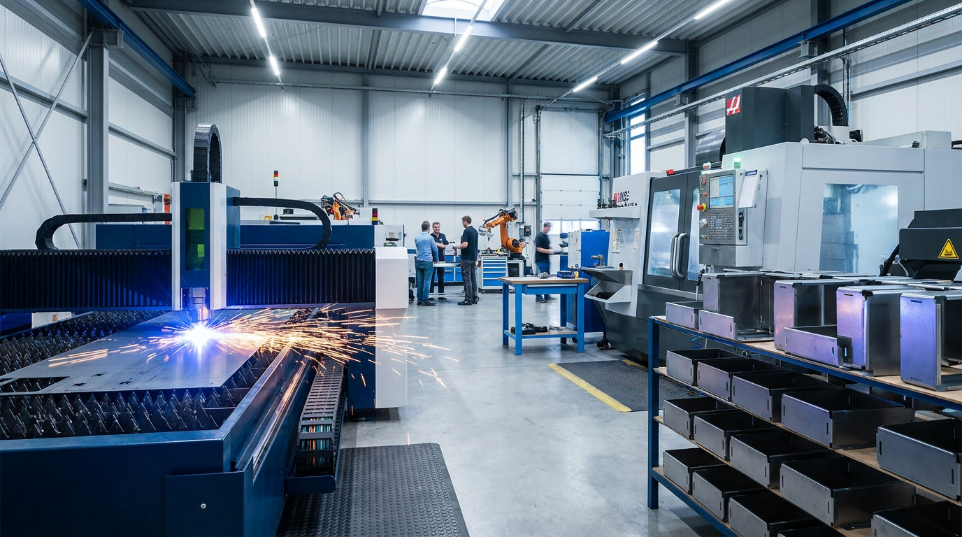
Whether you are designing a sleek electronic enclosure, prototyping a structural chassis for an electric vehicle, or sourcing custom hardware for industrial machinery, custom metal fabrication is the backbone of hardware product development. Yet, for product designers, mechanical engineers, and procurement managers new to the field, navigating the manufacturing landscape can be daunting.
Choosing the wrong process—such as specifying a complex 3D CNC machined part when a bent sheet metal bracket would suffice, or selecting an incompatible metal alloy—frequently leads to inflated production costs, unexpected lead-time delays, and costly part redesigns.
This comprehensive custom metal fabrication guide breaks down the fundamental manufacturing processes, compares the core technologies (sheet metal fabrication, CNC machining, and laser cutting), examines material selection trade-offs, and provides actionable design for manufacturability (DFM) rules to ensure your parts are production-ready.
What Is Custom Metal Fabrication? (System vs. Specific Method)
To build a solid foundation, it is vital to distinguish between a manufacturing system and an individual processing method.
Sheet metal fabrication is an overarching manufacturing system. It encompasses a sequence of operations—such as cutting, press brake bending, hardware insertion, and welding—that transform flat metal stock into functional three-dimensional parts and structural assemblies.
Conversely, CNC machining and laser cutting are specific material removal and cutting techniques. Laser cutting is frequently utilized as the initial flat-cutting stage inside a sheet metal workflow, while CNC machining is a standalone subtractive process used when solid blocks or thick plates require intricate 3D features, threaded holes, or ultra-tight tolerances.
Understanding how these technologies interact enables engineering teams to leverage hybrid manufacturing strategies, combining laser profiling, sheet bending, and secondary CNC operations to optimize both unit cost and part performance.
Decoding the Three Core Fabrication Technologies
Every custom metal part begins with raw stock. How that stock is transformed depends on the physics of the cutting and forming mechanism.
Raw Metal Stock → Primary Cutting (Laser Profile / CNC Blank) → Forming (Press Brake Bending) → Assembly (Welding / Hardware)
1. Sheet Metal Fabrication: Cutting, Bending, and Assembly
Sheet metal fabrication converts flat stock—typically ranging from 0.5 mm to 6.4 mm (0.020 in to 0.250 in) in thickness—into rigid, lightweight enclosures, panels, chassis, and mounting brackets.
The workflow relies on four core stages:
Flat Profiling: Blanking the 2D perimeter and internal cutouts using high-speed fiber lasers or CNC turret punches.
Forming and Bending: Using CNC press brakes with specialized punch and die tooling to bend the flat blank along programmed bend lines.
Hardware Insertion: Pressing self-clinching threaded fasteners (such as PEM nuts, studs, and standoffs) into laser-cut holes to create load-bearing threads in thin sheet.
Joining & Assembly: Uniting multi-part assemblies through spot welding, TIG/MIG welding, or mechanical riveting.
For complex assemblies requiring tight seam fits and structural integrity, partnering with specialized providers offering integrated custom sheet metal fabrication services ensures seamless transition from flat CAD pattern to final assembled product.
2. CNC Machining: Subtractive 3D Manufacturing
CNC (Computer Numerical Control) machining is a mechanical, subtractive manufacturing process. A computer-guided, high-speed rotating cutting tool (such as an end mill or drill bit) physically carves material away from a solid block of metal (billet) to yield the desired 3D geometry.
Key characteristics of CNC machining include:
True 3D Capabilities: Capable of creating deep internal pockets, complex compound curves, stepped wall profiles, counterbored holes, and precision internal/external threads.
Exceptional Accuracy: Capable of achieving linear tolerances of ±0.013 mm to ±0.05 mm (±0.0005 in to ±0.002 in), making it the gold standard for bearing seats, sealing surfaces, and high-precision mechanical fits.
Mechanical Material Removal: Because cutting is purely mechanical, CNC machining eliminates heat-affected zones (HAZ) and thermal distortion, preserving the original metallurgical structure of the alloy.
To explore how precision machining achieves extreme repeatability across production batches, review detailed engineering insights on CNC machining precision and tight tolerances.
3. Laser Cutting: High-Speed Thermal Profiling
Laser cutting is a non-contact, thermal cutting technique. A concentrated, computer-controlled laser beam melts, vaporizes, or burns through metal sheet along a pre-programmed 2D vector path. A high-pressure assist gas stream blows the molten metal out of the cut slot (kerf), leaving a crisp, narrow cut line.
Modern industrial fabrication centers rely heavily on Fiber Lasers, which offer key operational advantages:
Extreme Speed: Cuts thin to medium sheet metal (up to 25 mm) significantly faster than mechanical routers or plasma cutters.
Narrow Kerf & Intricate Detail: With kerf widths between 0.08 mm and 0.15 mm, fiber lasers create sharp internal corners and fine geometric details that mechanical tools with finite tool radii cannot produce.
Assist Gas Selection:
High-Pressure Nitrogen (N₂): Acts as an inert shielding gas. It prevents oxidation during cutting, producing bright, oxide-free edges on stainless steel and aluminum that are immediately ready for welding or powder coating.
Oxygen (O₂): Acts as a reactive gas for carbon steel. The exothermic reaction increases cutting speed through thick plate, though it leaves a thin oxidized layer that requires light deburring prior to painting.
Facilities utilizing advanced multi-kilowatt precision fiber laser cutting services can rapidly convert flat CAD sheets into hundreds of burr-free blanks with minimal material waste and zero physical tool wear.
Key Takeaway: Laser cutting excels at fast, high-volume 2D flat profiles; CNC machining dominates complex 3D depth features and tight tolerances; sheet metal fabrication combines cutting and bending to create strong, lightweight 3D structures from flat stock.
CNC Machining vs. Laser Cutting vs. Sheet Metal: The Direct Comparison
Evaluating process capability across geometric, tolerance, and economic factors is essential during the early prototyping phase. The matrix below outlines how these processes compare across key engineering metrics.
Feature / Metric | Sheet Metal Fabrication | CNC Machining | Laser Cutting |
|---|---|---|---|
Primary Geometry | Folded 3D structural enclosures, brackets, panels | Solid 3D complex features, pockets, threads, contours | Flat 2D profiles, intricate cutouts, hole patterns |
Material Form | Flat sheet stock (0.5 mm to 6.4 mm typical) | Solid billets, bars, thick plates, castings | Flat sheet & plate stock (0.5 mm to 25 mm+) |
Achievable Tolerance | ±0.1 mm to ±0.5 mm (dependent on bends) | ±0.013 mm to ±0.05 mm (high precision) | ±0.05 mm to ±0.15 mm (high 2D accuracy) |
Internal Corners | Radiused at bends; sharp on cut profile | Must include fillet radius matching cutting tool | Extremely sharp (0.08 mm kerf radius) |
Production Speed | High (once flat cut and press brake set) | Moderate to low (longer cycle times per part) | Ultra-high for 2D sheet profiles |
Setup & Tooling Cost | Moderate (press brake setup, standard dies) | High (custom fixturing, multi-axis programming) | Low (no physical dies; direct CAD software nesting) |
Secondary Steps | Deburring, hardware insertion, welding, painting | Deburring, surface plating, anodizing | Bending, tapping, deburring, welding |
Understanding these CNC and laser cutting tolerance tradeoffs helps engineers avoid over-specifying tolerances on flat sheet features where laser cutting provides adequate precision at a fraction of the cost.
Material Selection Guide for Custom Metal Parts
Selecting the correct metal alloy balances structural strength, weight, corrosion resistance, formability, and total unit cost. Below is a comparative breakdown of the four most widely specified alloys in custom metal fabrication processes.
Aluminum 6061-T6 ► High Strength & CNC Machinability (Rigid Structural Frames)
Aluminum 5052-H32 ► Superior Formability & Marine Corrosion Resistance (Bent Brackets)
Stainless Steel 304 ► Sanitary, High Strength & Heat Resistance (Food & Outdoor Equipment)
Carbon Steel A36 ► Cost-Effective Structural Steel (Chassis, Heavy Equipment)
1. Aluminum 6061-T6
Key Characteristics: Heat-treated precipitation alloy with high yield strength (~276 MPa) and excellent structural rigidity.
Machinability vs. Formability: Produces crisp, clean chips during CNC milling, making it the top choice for machined parts. However, its T6 temper makes it prone to cracking along tight bend radii during sheet metal forming.
Best Applications: Machined mounting blocks, structural frames, aerospace brackets, heat sinks.
2. Aluminum 5052-H32
Key Characteristics: Non-heat-treatable alloy alloyed with magnesium, offering outstanding ductility and marine-grade corrosion resistance.
Machinability vs. Formability: Exceptional formability allows sharp 90-degree bends without surface cracking. Conversely, its ductility makes it "gummy" during CNC machining, leading to tool wrapping if cut parameters are not tightly controlled.
Best Applications: Sheet metal enclosures, marine hardware, automotive panels, electronic chassis.
3. Stainless Steel 304 / 304L
Key Characteristics: Austenitic chromium-nickel stainless steel providing superior corrosion resistance, high tensile strength (~505–750 MPa), and excellent aesthetic appeal.
Fabrication Considerations: Exhibits work-hardening behavior during CNC machining and press brake forming. Requires higher press brake tonnage and careful calculation of springback allowance.
Best Applications: Food processing equipment, medical devices, outdoor enclosures, chemical tanks.
4. Carbon Steel A36 / Q235
Key Characteristics: Universal low-carbon structural steel offering high strength, excellent weldability, and low raw material cost.
Fabrication Considerations: Readily laser-cut using oxygen assist gas and easily formed on press brakes. Requires protective surface coating (such as powder coating or zinc plating) to prevent atmospheric rusting.
Best Applications: Heavy machinery frames, industrial mounting brackets, automotive structural supports.
Essential Design for Manufacturability (DFM) Guidelines
Adhering to proven design for manufacturability (DFM) guidelines during the CAD design phase eliminates common manufacturing defects, reduces scrap rates, and lowers overall production costs.
1. Hole Placement and Distance Rules
When laser cutting or punching holes in sheet metal, localized stress concentration and material deformation near edges and bend lines must be controlled:
Minimum Hole Diameter: Keep the hole diameter (D) equal to or greater than the sheet thickness (t):
Minimum Hole Diameter (D) ≥ Material Thickness (t)Hole-to-Edge Distance: Position the edge of any hole at a distance (Se) equal to or greater than the material thickness (t) from the sheet border to prevent bulging:
Hole-to-Edge Distance (Se) ≥ Material Thickness (t)Hole-to-Bend Distance: Place holes at a minimum distance (Sb) from the start of an internal bend radius (r) to prevent distortion during press brake forming:
Hole-to-Bend Distance (Sb) ≥ (2 × Material Thickness) + Inside Bend Radius (r)
2. Sheet Metal Bending & K-Factor Calculations
When metal is bent on a press brake, the outer fibers stretch in tension while the inner fibers compress. Between these zones sits the neutral axis, an imaginary plane that undergoes zero change in length.
The K-Factor is the ratio of the neutral axis position (t neutral) to the total sheet thickness (T):
K-Factor (K) = t neutral / Total Sheet Thickness (T)
For standard air bending on steel and aluminum, the average K-Factor typically ranges between 0.40 and 0.45.
To determine the exact flat pattern blank length in CAD software, calculate the Bend Allowance (BA) using the complementary bend angle (A in degrees), inside bend radius (r), and sheet thickness (T):
Bend Allowance (BA) = (π / 180) × Bend Angle (A) × [Inside Bend Radius (r) + (K-Factor × Thickness (T))]
Accurate sheet metal K-factor calculations ensure that bent sheet metal parts align perfectly with mounting hole patterns after forming.
3. Bend Reliefs and Minimum Flange Height
To prevent tearing at the edges of bent flanges:
Bend Relief Notch: Cut relief slots on both sides of a partial flange. The relief width (Wr) and depth (Dr) should be equal to or greater than the sheet thickness (t):
Relief Width (Wr) ≥ Material Thickness (t)andRelief Depth (Dr) ≥ Material Thickness (t)Minimum Flange Height: Ensure the flange length (Hf) is long enough to rest securely across the press brake bottom die opening during forming:
Minimum Flange Height (Hf) ≥ (2 × Material Thickness) + Inside Bend Radius (r)
4. Post-Processing & Welding Integration
For complex sheet metal weldments, incorporating self-locating tabs and slots into the 2D laser-cut flat pattern drastically reduces assembly fixturing time.
Where structural strength or leak-tight sealing is required, utilizing professional TIG and MIG welding assembly services ensures clean weld beads and structural integrity across stainless steel, aluminum, and carbon steel assemblies.
Pro Tip: Standardize inside bend radii across your entire part to match available press brake tooling (e.g., r = 1.0 mm for all 1.5 mm sheet bends). Changing bend radii across multiple flanges forces the fabricator to perform multiple tool setups, increasing setup labor charges.
How to Choose the Right Method for Your Project (Decision Framework)
Use this four-step decision logic to select the optimal manufacturing path for your custom metal component:
Evaluate Part Geometry:
Is the part primarily constructed from flat sheets with uniform wall thickness and bent flanges? → Choose Sheet Metal Fabrication (Laser Cutting + Bending).
Does the part require thick structural sections, pockets, internal steps, or threaded bores from a solid block? → Choose CNC Machining.
Is the part a flat 2D profile with intricate cutouts or holes and no bending? → Choose Laser Cutting.
Assess Tolerance Requirements:
If feature locations must hold tolerances tighter than ±0.05 mm (±0.002 in), specify CNC Machining.
If general tolerances of ±0.2 mm to ±0.5 mm are acceptable, Sheet Metal Fabrication provides superior cost efficiency.
Analyze Material Thickness:
For sheet stock under 6 mm, laser cutting combined with press brake bending offers rapid turnaround and low material waste.
For plates exceeding 25 mm or parts requiring deep 3D pockets, CNC machining is required.
Consider Production Volume & Budget:
Low Volume / Prototype: Laser cutting flat blanks eliminates hard tooling costs, making it ideal for rapid design iteration.
Mid to High Volume: Sheet metal fabrication scales efficiently as setup costs are distributed across larger production runs.
Frequently Asked Questions (FAQ)
What is the main difference between CNC machining and laser cutting?
CNC machining is a mechanical subtractive process using rotating cutting tools to carve 3D shapes out of solid metal blocks. Laser cutting is a non-contact thermal process using a focused light beam to cut 2D profiles through sheet metal stock.
Can laser cutting replace CNC machining for all custom metal parts?
No. Laser cutting cannot create 3D depth features such as blind pockets, countersinks, T-slots, or precision internal threads. However, fiber lasers excel at 2D perimeter cutting and hole profiling at significantly higher speeds than CNC milling machines.
Why is Aluminum 5052 preferred over 6061 for sheet metal bending?
Aluminum 5052-H32 possesses high ductility and elongation, allowing it to undergo sharp 90-degree press brake bends without surface cracking. Aluminum 6061-T6 is stronger and harder, making it ideal for CNC machining, but more prone to cracking when bent along small radii.
What is the purpose of a bend relief in sheet metal design?
A bend relief is a small notch or cut-out placed at the edge where a flange is bent. It prevents the material from tearing or deforming improperly at the corner transition during press brake forming.
Next Steps in Your Custom Fabrication Journey
Mastering custom metal fabrication is a continuous process of aligning product design requirements with shop-floor manufacturing capabilities. By choosing the right process—whether precision fiber laser cutting for rapid 2D blanks, CNC machining for intricate 3D features, or integrated sheet metal forming for lightweight structural chassis—you can achieve optimal quality while keeping manufacturing costs under control.
When preparing your CAD models for production, verify that your flat pattern blank accounts for correct K-factor bend allowances, ensure hole clearances follow DFM standards, and select an experienced manufacturing partner capable of handling your project from prototype to full-scale assembly.